 Custom Search
|
| boat plans |
| canoe/kayak |
| electrical |
| epoxy/supplies |
| fasteners |
| gear |
| gift certificates |
| hardware |
| hatches/deckplates |
| media |
| paint/varnish |
| rope/line |
| rowing/sculling |
| sailmaking |
| sails |
| tools |
| join |
| home |
| indexes |
| classifieds |
| calendar |
| archives |
| about |
| links |
| Join Duckworks Get free newsletter CLICK HERE |
|
|
| How to Create a 3D model from an Old Paper Plan |
by Jacques Mertens – Vero Beach, Florida – USA |
Part One - Part TwoOr Lofting on the Computer - Part TwoEntering Points from Two ViewsWe are going to look in detail at the fairing method we use with Rhino3D. We will create a plan view and a profile view, fair the lines in those two views and then use a Rhino tool named “curve from two views”. This will create fair lines in 3D. We know that there is a risk to deviate from the original points in one view while working in another but we'll keep an eye on that. Let's start by creating a plan view of the sheer line. This will be much easier than creating points in 3D. The coordinates (dimensions) for the sheer line in plan view are all on one row of the table of offsets, one point at every station. We start at 0 for station 0 then add a line at each station, every 22”. Using the example above, at station 8, the sheer point is at 4-6 which means 54”. We do that for each station then join the points with a curve that passes through the points. That curve will require fairing.
What you see above is not an exaggeration, it is truly what the Atkins table of offsets for the Shoreliner produces. How to FairFirst, let's correct some unfairness due to typos. This happens a lot. With our Shoreliner plan, one dimension in the table of offsets showed a big jump from 2' to 3'. At station 5, the sheer height went suddenly to 3-1-3/8. When we tried 2-1-3/8, it was much better. This was a drafting typo that we corrected. Still, the curve had bad kinks, we couldn't build a boat from that. There are many different fairing techniques but in our office we like to fair mathematically by reducing the degree of the curve and the number of points. Rhino3D has a tool to rebuild a curve by changing it's degree and setting the number of points. We get there by selecting the curve and clicking on edit/rebuild.
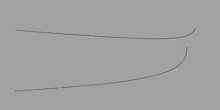
In the picture above, the red line is the “rebuilt” one with less control points. The original Atkins lines had 16 points and we interpolated as 3rd degree curves. 3rd degree is already “tight” but that is our default setting when creating the curves. Keep an eye on the line that show “maximum deviation”. Let's do point count 3 and degree = 2. It's nice and fair but the max. deviation is 1.6” = unacceptable. In general, for this type of lines, 5 or 6 points 2nd or 3rd degree will work and produce a deviation of less than 0.25” from the original lines. If possible, go for a 2nd degree curve. Keep in mind that is only a first 2D fairing. We will get closer in 3D. Using that technique, we will create plan and profile views of the sheer and chine then fair. Some of those lines cam be really bad. We have to use good judgment and guess what the intent of the designer was. You may find that one or two points really mess up the fairness of a curve. The lofter (that's us) can decide to move those points. Fair the best you can in 2D, save and go to the next step. Create 3D Curves With the lines faired in plan and profile, we can now create the 3D lines . Once the 3D curves are created, we must fair them again. Select one of the curves and turn the control points ON. The 3D curves have more points than the 2D curves. We will fair them in 3D using the same rebuild command: try to reduce the degree and the number of points as much as possible while staying close to the points.
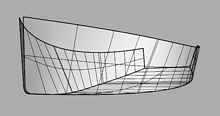
In the picture above, the faired sheer has 5 points, the chine 6, 2nd degree curves. Compared to the Atkins table of offsets, with the exception of a few typos or drafting mistakes, all points of the table of offsets are within 3/8” of our hull, 80% of the points are at 0.125” (1/8). You can use the Rhino curvature graph to check but curves of 2 or 3rd degree with only 4 or 5 points are always fair. Plywood will bend easily around fair curves, the hull will be easy to plank and look good. Plywood PanelsFrom the 3D curves, we can now create the hull surfaces, the hull panels, in this case plywood. This is done in Rhino3D with the command /surface/loft/developable surfaces. To use that command efficiently requires some experience but you will get a feel for the surface by looking at the ruling lines and using the surface analysis tools. Try to unroll the surfaces, their unrolled area should be very close to the original surface, within 0.1%.
Note the gap at the stem: Atkins shows a laminated stem post. Those who want to build a plywood composite boat will build a fiberglass stem post but that is another story. That's it for the lofting: we created a very fair hull surface from a table of offsets. The method we used is similar to what a loftperson would have done on the shop floor with wooden battens but much more accurate and faster. The next step will be to extract components like unrolled hull panels, stations for the molds, frames and everything we need to build the hull. For us, the goal was to produce a CNC kit and at this stage, we have enough accurate data to cut the plywood for the hull and the molds for the jig. The builder will use the Atkins drawings for rudder, CB and rig. Those who want to customize the design now have a good reliable starting point. Add a deck, appendages, sail plan and do some basic math for the weights if necessary. In this case, Atkins supplies scantlings for a plywood version. If we build her as designed, the weights will be on target but many builders will prefer to add some fiberglass here and there on thinner ply. That will require some weight editing and will be the subject of another discussion. |
To comment on Duckworks articles, please visit one of the following:
|
 |


