| How safe is safe enough? Since I acquired an
elderly 26’ Norman Cross-design trimaran two
years ago, I have been learning to sail and reading
lots about blue-water cruising (which I expect never
to do!). Scanning my bookshelf, I see Sensible
Cruising, The
Coastal Cruiser, Cruising
in Comfort, The
Case For the Cruising Trimaran, The
Finely Fitted Yacht, and so on.
Even though I expect never to need tips from Heavy
Weather Sailing, I figure there
is no premium on ignorance or poor preparation.
Part of safe sailing is to be visible to commercial
traffic so a freighter does not run you down without
even noticing. Here on Northumberland Strait just
north of Nova Scotia, heavy commercial traffic is
not really a problem—perhaps one barge tow goes
by in a day and the ferry from Wood Islands (where
I moor) runs on a 90-minute interval. I am quite confident
the ferry has someone looking out all the time as
well as looking at the radar, and a sailboat is highly
visible during the day. Still, a radar reflector seems
like a good idea. When I got my sailboat, the previous
owner tossed in a 3-plate radar reflector (an “octahedral”
reflector which was, by hindsight, too small at 4
¾” to be at all effective), which I hung
near the mast top. Unfortunately, it flopped around
and clanged horribly up there even in calm weather,
so this Spring I was going to mount it rigidly at
the mast top, but then I started to think about how
it works and figured it wasn’t going to reflect
all the way around.
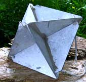 |
When I got my
sailboat, the previous owner tossed in a 3-plate
radar reflector (an “octahedral”
reflector) which was, by hindsight, too small
at 4 ¾” to be at all effective.
click image
to enlarge |
Comparing Reflectors
I was reading my way through my West Marine Catalog
and came to radar reflectors (page 205 in the 2007
catalog). The catalog makes a great read just for
the little bits of information they scatter through
it even if you are not shopping at the moment. It
may seem odd to you, but then I knew a fellow who
used to read the encyclopedia for entertainment. I
found they sold reflectors at prices from $25 to $600.
Being on a strict boat budget, I decided I could make
a better, and hopefully cheaper, reflector.
I discovered in a web search that US Sailing did
an evaluation
study of commercial radar reflectors
in 1995. It is an excellent article. It defines terms
and establishes a goal for an acceptable reflector.
The authors decided a RCS (Radar Cross Section) of
2.5m2 was the minimum to be useful—the reflection
that comes back from a sphere with a viewed area of
2.5 square meters—about 6 feet in diameter!
Fortunately, there are much more effective shapes
for reflecting radar. (I know, everybody wants a shape
to make their car invisible to police radar!) The
study was very revealing in that almost none of the
reflectors tested gave what they considered a minimum
acceptable performance. My tiny triangular one was
there, totally insufficient! An ideal reflector would
return a strong signal to a distant ship’s radar
detector when the ship is on the horizon anywhere
around the boat. Actually, unless your reflector is
gimballed, if you have a monohull
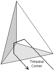
Figure 1: Trihedral corner reflector |
sailboat that works best at about a 30 degree heel,
or are travelling in a rough sea, you really want
a reflector to return even if it is tipped! For uniformity
at all angles, you cannot do better than a sphere,
but for some reason no one wants a 6’ sphere
at the top of their mast!
Trihedral Basics
Years ago, a friend who loves astronomy talked about
a corner cube reflector set up by the astronauts on
the moon. You could do experiments bouncing a laser
beam off the moon. The reflector is the thing of interest
here. It did not have to be set up precisely—if
it did, the distance to the moon would certainly exaggerate
any errors! The secret is a corner cube. Imagine cutting
off a corner of a cube, getting three triangles that
are at right angles to each other (“orthogonal”).
It turns out that they will bounce light back in the
direction from which it came as shown in figure 1.
The shape is a “triangular trihedral”.
With these three perpendicular surfaces, no matter
what angle the light arrives from (as long as it is
still “seeing” all 3 surfaces) bounces
in turn off all three surfaces and returns at just
the angle from which it arrived. As the reflector
turns less and less light bounces back until at angles
outside the corner, nothing
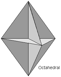
Figure 2: Octahedral radar reflector |
bounces back. Conversely, the closer the beam is
to the axis (the point where all 3 sides are the same
angle to the beam) the more light bounces back. Replace
the mirrors with almost any metal and you have a shape
that reflects radar signals about the same way a corner
cube mirror reflects light.
Applying this to my tiny 3-plate unit in figure 2
(called an “octahedral” because the plates
form eight trihedral corners), the reflection as shown
would vary greatly as I walk around it. Remember,
unless the path hits all three surfaces, the radar
beam bounces off at some other angle and lost. The
most return comes when the corner is straight on,
and almost nothing comes when one of the sides is
in line—even though I can see a lot of surface,
the reflector is not sending the signal back unless
all three surfaces are involved. That means that positioning
my octahedral unit with one plate horizontal is the
worst possible orientation. Unless it is exactly horizontal,
a slight tip, projected over several miles, will send
the return far above or below the distant ship.
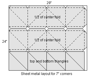
Figure 3: Sheet metal layout |
Much better is to position one corner up and one
down (called the “holds water” position
because, if it you seal the joints, the unused upper
corner would do just that). I do not need to worry
about radar coming from overhead! With one useless
corner pointing up and one pointing down the remaining
six corners have to cover 360 degrees—each corner
is responsible for 60 degrees. Unfortunately, with
this orientation the corners are not facing straight
out—one axis is up by about 16 degrees and the
next axis points down by the same angle.
The US Boating article liked the “double hold
water” orientation. With one plate oriented
vertically with an edge along the top (build a model
and try it!), you get four corners facing out each
covering 90 degrees, but their axes are exactly horizontal—not
tipped up and down—which gives the largest reflections.
That orientation gives four very strong peaks but
drops to almost no reflection in-between.
Designing your own
Scratching my head, I decided that stacking two separate
octahedral reflectors with one rotated 45 degrees
to the other would give eight straight-on reflectors
and fill in the nulls around the circle. Might there
be a better way than the 3-plate design? I started
with construction paper, making up individual trihedral
corners and fitting them together. To save space it
seemed that one set of four could have points up and
the second set could have points down. The corners
could fit into each other. The paper model revealed
that, if you accept some up and down tip of the corners,
I could build the whole reflector with 3 pieces of
sheet metal, given the right tabs and bends. My current
design (see figure 3) uses a 24" x 29" sheet
of aluminum roof flashing to make a unit about 8 1/2
inches high.
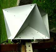
| Figure 4 - SIDE
VIEW - It is not too easy to visualize the shape.
The pictures are rotated to make the orientation
fit that of the final position at the top of the
mast. |
|
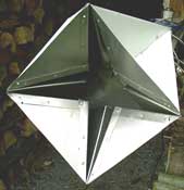 |
- TOP VIEW
- The top rectangular plate is removed so this
view looks into the inside, showing the inside
ends of each corner.
click images
to enlarge
|
The finished unit, figure 4, looks like a loudspeaker
array you might find on a pole at some sporting event.
I like the idea that a very good reflector can be
made for perhaps $15 in materials when the “unacceptable”
ones are $55 (or $25 for a foam-core plastic one)
and $250 for a lens-type reflector in West Marine's
catalog.I would hesitate to call this reflector an
invention—it is just a convenient way of bending
sheet aluminium and may already have been “invented”.
I intend to stick my prototype up on the mast at least
for a season (I'm sure it is better than the simple
3-plate units), but I have now gotten to the point
of doing some calculations that say it could be improved.
Construction Hints
I started to build the reflector to the pattern of
figure 3 using 14 gauge aluminum (which cost me almost
$4 a square foot) but I found it too difficult to
cut—I had to use a metal blade in a jigsaw rather
than tin snips—and I found it very difficult
to bend. If I had the right sheet metal tools it would
be a different story, but the folds are still difficult
and I found that using the thinner metal still gives
sufficient strength once all the bends are in place.
I easily cut out the pieces of figure 3 from aluminum
flashing with ordinary tin snips. Then I set out to
make all the folds. I suggest you practice with a
small model cut from construction paper (my models
were dark blue and black because my grandson cannot
draw in crayons on the dark pieces in the package)
and assembled with Scotch® tape. Getting the folds
took some head scratching again. A vice can almost
work if the jaws are wide enough or if you put longer
sticks of wood between the jaws and the metal. Or
you could clamp the metal to a table with C-clamps
and a piece of wood. I happened to have an antique
saw sharpening vice which I’m told my grandfather
used to sharpen hand saws—now that goes back
at least 70 years! You can make the bends with your
bare (or gloved) hands or help it out with a mallet
or hammer. As you look at the pattern, the two long
strips are the bending challenges (you could make
individual corners and fasten them together if you
prefer, but that takes more sheet metal and I hate
waste). The sequence that worked for me was to bend
the left-most straight (short) side toward me to 90
degrees (it would become the boundary between two
orthogonal sides of a corner), and then bend the next
diagonal back flat (180 degrees). The intersections
did not end up at quite that angle in the end but
it was easier to work with that way. Then I bent the
first two tabs forward 90 degrees. I continued the
process on down the strip and ended up with half of
the center pieces. I did the same with the second
strip and had the full 360 degree center. Next, I
fastened the two pieces together at the ends (into
a sort of circle). I did all the fastening of the
aluminum pieces with short 1/8” aluminum blind
pop® rivets. I figured aluminum sheet and aluminum
rivets would avoid galvanic interactions. I had to
drill 1/8” holes through the two pieces I was
joining but the rivets made it easy to fasten from
either side—not everything was very accessible
as it took shape. Once I had connected the center
strips together, I fastened the eight remaining individual
triangle pieces to the side tabs to form the eight
trihedral corners. The result was quite stiff. The
top and bottom surfaces are 10" x 10" squares
and while you can use plywood or heavier aluminum,
I chose the latter because I hated to waste all that
14-gauge aluminum from the first attempt! In order
to get wiring up through fro the radio antenna and
the anchor light (as well as my weather station),
I fastened the top surface with sheet metal screws
(stainless since I could not find any aluminum screws
such as were used for add-on aluminum storm windows
in the old days).
How Well Should It Work?
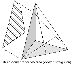
Figure 5: Graphical model of off-axis effective
area |
The US Boating article is excellent in that it gives
a way to get a calculation of real effectiveness.
Figure 1 of their article, when blown up
to be readable, gives formulae for a variety of shapes
including the triangular trihedral (you can also calculate
for circular and square trihedrals). For my triangular
design, the maximum RCS (on axis) is:

where  is the length of one side of the triangle sides (about
7" in my case) and, for X-band radar,
  is about 2.5 cm. Converting units and cranking out
the numbers (its been a long time since I’ve
used scientific notation!) I get a maximum (on axis)
of about 7 m2 as the RCS of my 7” corner. A
little piece of aluminum about 10” on the long
edges looks to distant radar like a sphere almost
10’ in diameter! Notice that the RCS goes up
with the fourth power of the side length.
Size matters.
So how well does my design work? Setting the finished
reflector on the kitchen table and staring at it as
I turned it around, I began to see that the key is
to find how much of the part I’m seeing still
gives 3-bounce return—on axis a beam arriving
anywhere within the projected equilateral
triangle makes the requisite 3 bounces, but as it
rotates, less and less of the projected triangle represents
3-bounce region.. After a lot of head scratching again,
I think I have a way to calculate the relative off-axis
reflectance. Look at figure 5, which shows a hypothetical
reflector at some angle off-axis. If, for one side,
I draw lines from the outer corners at the same
angle on the other side of the back edges, I
mark off the area that works for the reflection from
one side. Think of it as the reflected shadow of the
one side. Then do the same for the other two sides
and get the area that is shared by the reflection
of all three surfaces. Now I have the area that will
have three reflections—anywhere else in my view
of the reflector will miss at least one reflection
and send that incoming signal off somewhere else.
In figure 5 I brought out the striped area as the
only valid reflector area for that orientation—at
a guess it looks like about 40% of the on-axis orientation.
If this were a view of my 7” (7 m2
RCS) that would mean that this orientation gives an
RCS of 40% of 7 or 2.8 m2.
For A First Cut, Measure - Don't Calculate
How can I get all the areas? By the time I could
re-learn all the solid geometry and trigonometry that
I almost learned in college that I would need to direct-calculate
the angles and areas, I would have ceased to care!
Instead, putting the finished reflector on my kitchen
table, I measured the projected width and apparent
angles of the outer edges and the inner sides with
a protractor. This was not high precision, but I needed
some ballpark numbers to go on. Searching the web,
I found a SITE
that solves angle-side-angle and side-angle-side
triangles (again, it looked like too much work to
do it all with the ½bh formula). The results
are shown in Figure 6 for the 7.5 degree angle intervals
I measured and computed areas. Bad news! Even though
straight on should give 7m2 for the RCS, because of
the up/down tip, the best I get is 31%—12 degrees
off axis had dropped off 70%. The good news is that
the adjacent corners pick up the slack as I had hoped
and the fluctuation is about 2:1 around the reflector.
The reflection is present all the way around—just
not enough.
A Little Bigger Is A Lot Better
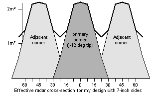
Figure 6: RCS for my design vs. angle |
Now, do you remember that fourth power? If, as the
article says, I need a minimum of 2.5m2 for the RCS,
I can just make it enough bigger so the minimum 1.18m2
RCS scales up to 2.5. How much bigger? With a fourth
power I need the fourth root of 2.12 or a scale up
of 1.2. My 7” edge dimension can go up to 8.46”
(or 10” diagonals go to 12”). That is
hardly enough to see and can easily be done with a
longer piece of roof flashing. Scaling up to fit still
on 24” wide flashing, if I go to 60” instead
of 29” I can fit two widths of 10” sides
(14” diagonal) and fit the extra corners at
the end for less waste. That is better than a fourfold
increase—my next reflector could have a minimum
of 5m2 RCS or, as you rotate it, double to quadruple
the minimum!. I expect by next season I will be restless
enough to build the larger reflector—going from
10” wide to 14” will hardly be visible
from the dock.
What About Rough Seas And Heeling Sailboats?
I have not really analyzed the reflection as the
mast tips. I can say that the fact that the corners
are tilted up and down means that some would do better
when the mast is tipped away and some would do better
when the mast is tipped toward the source. The gain
would be a factor of 3 or 30m2 for straight
on axis! In that orientation, a 24 degree tip would
bring the value back down to original horizontal value.
On the other hand the corners pointing the wrong way
would now be 36 degrees off axis—almost no return
at all. In a tossing sea, hopefully the motion will
occasionally bring the reflector to a good position
at the moment the radar beam sweeps past the boat.
I suppose I could study the period of rotation of
radar antennas as well as the periodicity of the sea
to get a probability of getting a good reflection,
but again, life is too short. I will function on the
theory that the time I need the reflector the most
is in a thick fog when the sea is calm and even monohulls
are not heeling much.
Conclusion
I liked the end of the US Sailing article where they
say something like, "Even though they barely
work, you should still stick one up there—it
can't hurt and might help.” I think my design
is simpler than the lens units and can be fabricated
at home without any special skills. Made a little
bigger, it should be far better than the units on
the market for small boats. I can’t imagine
making it gimballed to give better heeling when the
boat heels or bounces on the waves, but then a few
months ago I couldn’t imagine designing a reflector
myself dither. Who knows?
Thomas Schultz
schultz@pei.sympatico.ca
Addendum
Dec, 2008
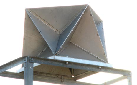
In my article last year about making your own radar reflector, I may have mentioned that the design is probably not new. Later that year I happened to notice the markers on each side of the channel leading into the harbour here on PEI. There is a large neon-orange surface as well as a light, but additionally, at the top is an aluminum structure shown in the attached picture. If it isn’t the same structure as I described! Clearly I cannot apply for a patent (I had no intention of doing so) and someone else had thought the same series of thoughts before me. I suspect the Coast Guard buys them from someone else, and the design may be patented by whoever constructs them, but I can’t imagine that an individual making one for their own use would be at any risk of a lawsuit. I have never seen the design advertised for use on boats in any of the marine supply catalogs, but I would think that the patent-holder (if any) ought to go into business for the marine pleasure market since the other devices are so totally inadequate.
Tom Schultz
*****


|