| by
Max Wawrzyniak - St Louis, Missouri - USA
Fitting
a Sailboat with an Outboard Motor
When the Boat was never Intended
to Have an Outboard Motor
|
 |
Well, it's the morning of April 15th, 2007 and the
sun is shining. Although a mite chilly outside now
the temp is supposed to rise into spring-time range
in just a few hours. A beautiful morning and I am
thoughly "bummed-out."
I was supposed to be running in a marathon this morning
but a knee injury has kept me side-lined.
So I guess I will write another column and later
will work on my self-designed kayak I have been building.
I have a cup of hot coffee handy, have the Destin
(Florida) Pass webcam
open on another screen, and have a subject to address
with this column.
A few years ago I decided to build a sailboat. My
experience with sailboats at that time was severly
limited so I selected what I felt was the simplest
and most practical sailboat design that I could find:
a Jim Michalak AF3.
It was certainly simple and easy
to build, but after overnighting on it
a few times I decided that I really should have built
something a little bigger, such as an AF2
or a Normsboat,
but the basic concept of the boat was a good choice.
After a few years I sold the AF3 and at some point
will build a slightly bigger boat in the future.
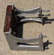 |
The fixed (non-adjustable)
bracket that was given to me some time in the
distant past. |
Although some of Jim
Michalak's sailboat designs such as the
Normsboat and the Mayfly
16, for example, feature mounting arragements
for a small outboard motor, the AF3 did not. Being
an inexperienced sailor, I felt the need for the "security
blanket" of an outboard so I had to devise the
mounting arrangmeents on my own. After picking over
my collection of outboard motors I finally decided
on (2) that I felt would be suitable for the AF3.
The first was a 1945 Neptune 2hp while the other was
a 1949 Gale 1.5 hp. Both engines were already in running
condition and neither engine was so "collectable"
or valuable that a dunking during a capsize was result
in a major finacial hit. The Neptune, in fact, had
a damaged crankshaft and I felt it's time was limited
anyway, so it became the primary engine for the AF3.
The usual mounting arrangment for outboards that
Jim shows in his plans is a motor "well"
between the transom and the "lazarette"
compartment. I considered incorporating such a well
into the AF3, but this would have greatly reduced
the size of the lazarette compartment, and the bouyancy
of this compartment was key to the "self-rescueing"
aspect of the the AF3 design. I decided that a bracket
mounting of some sort would be best.
Most of you will be familar with the adjusting motor
brackets so often seen on production sailboats. These
brackets lift the outboard clear of the water when
the motor is not in use, and lower the outboard when
it is to be run. These brackets are readily available
but they do cost money and they are a bit big and
bulky for a boat as small as the AF3, which has a
very small transom. Someone had given me a fixed bracket,
one that does not adjust up or down, and I decided
to use that bracket with some modifications. I could
also have constructed a fixed bracket from wood, with
long bolts passing all the way from the transon to
the motor mounting board.
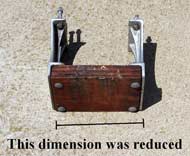 |
A new motor
mounting board would be made just barely wide
enough to handle the small outboards chosen
to power the AF3. |
Jim M usually suggests mounting the rudder off-center
to one side, and mounting the outboard off-center
to the other side, on boats with narrow transoms.
Being a traditionalist, I wanted my rudder mounted
on the centerline, with the outboard off to one side,
which was going to complicate matters. With only half
of a very narrow transom to work with the total width
of the bracket had to be minimized.
One of the attributes of the (2) outboards that I
selected was very narrow transon clamp spacing, meaning
the the engines required a minimum of width of area
upon which to be clamped. The motor bracket that I
used consisted of (2) cast aluminum arms with a wood
motor mounting board bolted to them. I removed and
discarded the wood board and replaced it with another
board witch I laminated from plywood. This new board
was much narrower than the original board and in fact
was just barely wide enough for the small motors to
clamp to. Many other small motors, especially modern
ones, would not clamp to such a narrow board.
Deciding exactly where to mount the bracket was another
concern. If the bracket was mounted too close to the
centerline of the boat, the propeller would hit the
rudder when the rudder was hard-over. The further
away from the centerline the bracket was, the more
likely the motor would get dunked in a capsize to
that side.
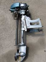 |
Once the proper
postioning of the outboard was determined, the
outboard was clamped to the bracket so the exact
postion of the bracket on the transom could
be found. |
Another concern was how high to mount the bracket.
The AF3 has a lot of "rocker" to its bottom.
A lot of rocker and the small size of the boat means
that a person moving forward or aft is going to cause
a large change in the trim of the boat. In other words,
If I walked forward into the cabin "slot,"
the bow was going to go down and the stern up. If
I went to the rear of the cockpit, the bow would rise
and the stern would drop. Both of the motors that
I intended to use were so-called "short shaft"
engines, meaning that they were intended for planing
boats with transoms about 15 inches tall. Since the
AF3's hull is not a planing hull, this measurement
is not particularly useful. Here is what is important:
When I walked forward and the stern rose, I did not
want the propeller or the cooling water intake of
the motor to come out of the water, When I went aft
and the stern fell, I did not want to submerge the
powerhead of the engine. Finally, I needed to be certain
that there was enough clearance between the outboard
and the transom so that the motor could be tilted-up,
and so that the starter rope could be pulled. An outboard
mounted on a bracket very low on a transom often can
not be tilted-up, and often requires a "vertical
pull" starter rope.
The final concern was structural. The AF3's transon
was not designed to take the weight or thrust of even
a small outboard motor. As I also intended to use
foot holds on the rudder for reboarding the boat,
I built the transom much heavier than designed. I
used 1/2 inch plywood instead of 1/4 inch, and I increased
the size of the framing a bit.
The waterlines on Jim's plans are usually marked,
and utilizing a straightedge laid across the drawings
I made a guess as to the vertical position of the
outboard. I used the straight edge to simulate stern-up
and stern-down conditions, keeping the center of the
straight edge on the marked waterline at the center
of the boat. Not being a naval architect, I had to
guess just how far the stern would rise or fall with
the weight of one or two people, but at least I had
the range of motion fairly established.
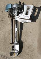 |
There needs
to be sufficient clearance between the top of
the outboard and the transom of the boat for
the outboard to tilt up. |
There are computer programs available that can predict
the results of just such a shift in the longitudinal
center of gravity, for you "geeky" guys
who want a more precise prediction. .
Next, I clamped the motor to the bracket (not yet
fastened to the boat) to establish the position of
the bracket when the motor was at the correct height.
With the motor still clampled to the loose bracket,
the motor was tilted-up in order to estimate the clearance
between the transom and the motor.
Taking measurements from the transom and rudder,
It was apparent that even with the narrowed bracket
there still was not enough space to one side of the
rudder to mount the outboard without the propeller
hitting the rudder when the rudder was put over more
than about 30 degrees. I did not want to install rudder
stops limiting the swing of the rudder to that side
so I decided that I would just have to be carefull
when motoring not to swing the rudder too much to
that side. In practice this was not too much of a
problem. although the rudder blade did show the signs
of occasional "rudder-propeller interface."
Once the desired position of the motor bracket was
decided upon, I drilled one hole and bolted the bracket
to the boat with one bolt and mounted the outboard
to double-check the clearances. Since all seemed well
I drilled the additonal (3) bolts and bedded and bolted
the bracket on. While everything looked good with
the boat on the "hard," I could not truly
check the vertical clearance of the motor until the
boat was launched.
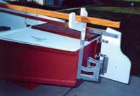 |
Bracket "arms"
bolted to the AF3. The motor mounting board
has not yet been added. Also shown is the fixed
mast crutch: not one of my better ideas. The
lower blade of the rudder has not yet been attached. |
The first time on the water revealed that I had postioned
the motor about as idealy as possible. Walking all
the way forward in the slot raised the stern to the
point where the outboard's propeller and water intake
were just barely in the water. Sitting at the very
stern still left the powerhead a comfortable distance
above the waterline, and the motor could be tilted-up
to just clear the water before the motor powerhead
hit the transom, limiting the amount of tilt.
Another concern in the installation was keeping the
sheet from becoming entageled in the outboard, a common
problem. I also needed a way to store the struck mast
on the boat where it would not be in the way of rowing
or other activities. My solution to these problems
was not so successful. I incorporated a mast crutch
into the motor bracket mounting. The crutch was not
removable, and the sheet was routed through a metal
ring on top of the mast crutch. Although the crutch
was very handy for storing the mast, the sheet not
only still became entagled in the outboard, it was
also become entangled in the crutch.
A much better arrangement would have been to mount
the rudder off to one side, so that the motor could
be moved more to the center where it wouild have been
much better protected from submergence during a capsize.
The propeller and rudder would have both benefited
from the increase distance between the two. Don't
know if this would have helped the sheet situation
but it could not have been any worse..
In the end, I probably could have gotten by without
the outboard motor at all. I had the oar ports and
oar locks that Jim shows on the plans, and used the
boat a few times on a lake where gasoline motors where
not allowed, and once rowed the boat a couple miles
when the old Neptune overheated. The boat was surpisingly
easy to row.
And I am a little bit better sailor now.
Happy Motor'n
Max

click
here for a list of Columns by Max Wawrzyniak |