THERE ARE MANY good mechanics
who do better working metal than
wood. It is for this group of craftsmen that Tintillee was designed.
Built of simple 12-gauge steel arcwelded to a simple bar and pipe
frame, Tintillee's construction follows the currently accepted methods
of fabricating a welded steel hull.
For the building of Tintillee here
is the size welder youll need: for
the 3/8-inch plates and bars, use 250
amperes at 45 volts. For the 3/16-inch
side frames, use about 200 amperes
at 35 volts. The 12-gauge plate ( 7/64
inch thick) will weld up properly at
lower current, say 120 to 130 amperes and not more than 30 volts.
Amperes is the quantity of current,
volts is the pressure. These currents will produce the proper heats. Use
shielded welding rod obtainable at
all welding supply stores and do all
your work "down weld" That is,
have the weld under the arc. Reverse polarity will help feed the
weld into the seam.
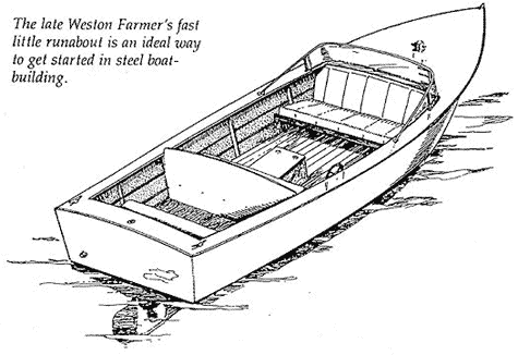
Now about Tintillee herself: we
have a simple V-bottom hull with
the proper entrance and breast for
an 18-footer which will drive from
10 to 16 miles an hour. Also, this
shape will plate topside without billowing between frames.
You will notice from the lines
drawing where the fore body
and aft body are shown in section
that there is a dotted line on the
forward frames. There will be a
tendency of the forward plates to spring away from the Frame. Let it.
The inner 1" x 3/16" stringer bars can
be sprung out to the skin, tack-welded, then welded to their slits to
provide final welded security for the
forward breast plates.

Because welded steel construction
is slightly heavier than wood — about
20 per cent in this size boat — one
cannot expect much planing action.
Rather, the boat is designed as a
bangabout for rough service, and
will do about 10 to 12 miles an hour
with a 25 hp Universal Utility Four,
about 10 to 12 miles with a Gray 33
Lugger, and will do about 16 miles
with a Gray 6-72, which is about the
top limit of economical powering.
As to building her. the Job is simple. Get a couple of 4' x 3' plywood sheets of ordinary grade, 1/4" thick
and use them for a floor, laid end
to end.
On this laying-out floor you fair
up your lines, reproducing to full
actual size the lines. It is on these
body plans that you lay out the flat
3/16" x 2-1/2" bars so as to tack-weld
them to size before removing and
running a bead into the joints.
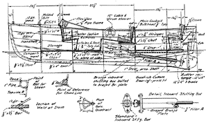
The keel assembly's laid out full
size as per the drawing fully detailed
below the lines drawing. From the
keel layout plywood templates are
lifted for all members.
Measure around the outer face of
the stem bar on this keel drawing
and cut a piece of stock for the 3/8"
x 22-1/2" stem bar. Take this to any
blacksmith shop, boiler shop or
forge shop and have them furnace
it and bend it to shape.

Cut the forefoot end of the stem
bar into a V-point, so that you can
fill the weld fillet up properly.
The keel bar is 13' length of 3/8"
x 4" bar. This will need no other
manipulation than the flame cutting
for the relief where the 1/2" x 1-1/4" steel bar skeg is welded. The skeg
itself is heated and bent to shape
after first drilling for the rudder
pintle.
Weld the stem to the keel bar.
Next, from a piece of 3/8" x 6"
strap. 10' long, flame cut the filler
plate Between keel and stern tube.
The waste end will form material for
the upper skeg filler plate and for
the horn bar and transom piece.
Weld the skeg fiUer to the keel
and stem assembly, using a down
weld with reverse polarity of 250
amperes at 45 volts. Also use a
welding rod of not over .025 carbon
content. This assembly may be tack-welded to hold it in shape before
running the continuous weld. This
continuous weld should be carried
along a few inches at a time on both
sides of the keel to avoid warping.
Note the elongated sluice hole in
the stern tube just forward of the
cutless bearing at the outboard end.
This is for the water stream which
lubricates the cutless bearings.
After the stern tube has been prepared for the inboard and outboard
bearings, it is welded into the keel
assembly. When this assembly has
been rapped here and there into flat
alignment, it is ready for erection.

Prepare some erecting sills in a
location where the boat may he
erected and later turned over. Rolling over will be necessary because
on both outboard and inboard, your
welding must be downward.
When proper sills and footing have
been provided, turn, the keel assembly upside down and shore into
place. Set frame No. 3, and temporarily tack it into its correct position,
taking care to have it plumb and
square; do this with other frames.
Next, the 12-gauge sheet for the
transom may be welded to the transom frame. This frame consists of
a 7/8" steel rod across the chine, and
of 1" I.P.S. pipe at the corners and
across the crown. The plate is cut
so that it comes tangent to all frame
members at greatest diameter. Thus,
the rod and pipe form the corners.
The top sides may be or a single
length of 12-gauge .017 carbon sheet
steel 30" wide and 20' long. They are
scribed, and flame cut to shape.
Next, fit in the topside stringers of
3/16" x 1" strap. These go into slots torched out for them just as they'll
stream into place. Now you can install the topside plates.

They must be carefully sprung in
place, adjusted here and there by
clamping, and then tack-welded.
The next step is to run in the fore
and aft bottom stringers. These are
welded at the transom rod, run
through the slots in the 3/16" x 2-1/2"
bottom frames, and cut off where
they stream into the chine rod at
the breast. Here they are left loose,
welded only after the bottom, plates
are on, and then secured by tack
welding when fitted.
It will be easier for the home
builder to plate from the transom to
about frame No. 2, then template the
forward breast bibs. thus assuring a
more easily handled plate which may
be rolled or peened into shape.
This completes the hull proper.
When all outside welds are completed, a disc sander with carborundum grit discs will fair off bumps in
welding and remove rust.
The boat must now be rolled over.
Auto jacks and blocking and ropes
can effect this task. The boat must
be leveled up again, right side up,
and the inboard welds completed.
When all the metal work has been
welded up, you have two choices as
to finishing the hull.

The best method calls for the
sandblasting of the hull inside and
out, with subsequent flame spraying
of zinc. Steel boats I have designed are running after 15 years of service,
initially plated with zinc like this.
The propeller shaft is of steel, and
so also is the propeller. The Michigan Wheel Company, Grand Rapids.
Michigan, is one concern, that makes
steel propellers.
The rudder is of the shape shown,
cut from an included rectangle 12"
x 16", with 1-12" of lead. Shaped as
shown it will not throw a "rooster
tail". Flush topped rudders do.
Tintillee will displace close to 2,198 pounds ready to launch. The hull
plating will use about 950 pounds of
steel, and the framing about 854
pounds. Hull fittings and engine
make up the difference.
Do not change scantling sizes—steel fools you badly on weights.
Built as described you'll have a
tough, serviceable, cheap boat.
WESTON FARMER

