Eighty to one hundred years ago, when a boat owner chose a boat design, the odds were very good that it included some sort of traditional sail. At the turn of the century and earlier, the Bermudian sail or Marconi sail was not very popular. Today, of course, the vast majority of sailboats are designed with a Bermuda rig even when that might not be the best choice. As a result, prospective builders who prefer a traditional sail plan are limited in the designs available. Nevertheless, it is possible to find a good hull design and then retrofit a sail plan that is more to the owners liking.
To accomplish this retrofitting process, the builder needs only a basic understanding of the factors that determined the placement of the original sailing rig, and why that placement creates what is called a “balanced rig.”
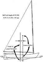
In the most simple terms, balance occurs when two points – the center of lateral resistance (of the boat) and the center of effort (of the sail plan) – interact in a manner that keeps the boat moving forward without rounding up into the wind (weather helm) or falling off downwind (lee helm). Figure 1 shows a typical location of both points. In most cases, the boat will balance better if the center of effort of the sail is in front of, or “leads,” the center of lateral resistance. The boat in figure 1 has a 7 percent lead (7 percent of the water line length), but the exact amount of lead varies from design to design. Most designs seem to have about a 5 to 10 percent lead.
Figure 1 - (at right) shows a typical location of the center of lateral resistance (of the boat) and the center of effort (of the sail plan).
(click image to enlarge)
|
 |
|
When retrofitting with a traditional sail, the builder must not change the existing amount of lead for the design. To keep from disturbing this balance, the traditional sail’s CE (center of effort) must match the CE (center of effort) of the sail it’s replacing. This is not as difficult a task as it might seem, assuming the builder is working from a set plans that has a sail plan. The sail plan will show where the CE is for the existing sail and where it is in relationship to the hull. The builder only needs to know the CE for the traditional sail and superimpose them to determine where the new sail and mast will fall.
Figure 2 shows the sail plan for a 14 foot skiff. It has the dimension of the main sail and jib, the height, rake and location of the mast, and the Combined CE for both sails. If the sail plan doesn’t show the CE it can be easily calculated.
|
Figure 2 - shows the sail plan for a 14 foot skiff. |
|
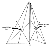
Figure 3 is a triangular main and jib, drawn to scale. (The same scale as the sail plan should be used or if the plans are in a book any convenient scale can be used). A line is drawn from one side (A) to the opposite apex (B). Then do this for all sides. The resulting intersection of lines at C and D is the theoretical or geometrical center of effort (CE) for each sail.
|
Figure 3 - is a triangular main and jib, drawn to scale. |
 |
|
The Combined CE of both sails is found by first connecting the individual CEs (points C and D in Figure 4). Then, at right angles to C and D, draw lines in opposite directions. In order to go the next step, the area of both sails has to be known. This will most certainly be on the sail plan but if not, calculate the areas using standard formulas. Once this data is at hand, transfer the area of the main sail into linear feet on line D/D’. A small scale should be used – 3/32 inch to 1 foot or smaller. Next, the area of the jib is transferred to line C/C’. Connecting points C’ and D’ will give the combined center of effort for both sails.
|
Figure 4 - The Combined CE of both sails is found by first connecting the individual CEs |
|
Once this has been established, it will be necessary to do the same for the traditional sail. But, before moving on to this step, some important questions should be answered. The primary question should be: Is the existing sail too large or too small? This would be the time to make adjustments. If other boats of similar type, size and weight have about the same sail area, then the area is probably about right. If not then an adjustment might be in order. The table in Figure 5 was compiled from a book written by E. C. Seibert, How to Design Small Boats, and published in 1947. According to the table, a 14 foot, unballasted shoal draft boat carrying 95 square feet would be on the low side, while 200 square feet would be high and 160 would be average. It should be noted that the sail areas considered to be on the low side by Mr. Seibert are, by today’s standards, more the norm. The skiff in figure 2 has a 90 square foot sail and the builder might want to adjust the area slightly up or down to suit the prevailing winds where the boat will be sailed. If the design is well tested, you can assume the area is about right and avoid any large changes in either direction.
|
Figure 5 - This table was compiled from the book "How to Design Small Boats" |
 |
|
Having settled on the sail area, the next question will be: To jib or not to jib? The existing sail plan might call for a jib but doesn’t necessarily mean the traditionally rigged boat must have one. One of the joys of traditional sails is simplicity. Stepping an unstayed mast and dealing with a single halyard and no boom are a few of the advantages of boats with traditional sails. In many cases, the advantages of better laminar flow created by the jib and the fast reduction in sail area by dropping it are offset by more halyards, sheets, and one more sail to deal with on a tack. If the builder decides that “less is more,” then the next step with be even simpler.
If a jib is not required, then all that is necessary is to draw the traditional main sail on a separate sheet of paper, remembering to use the same scale as the sail plan. Vellum is a good choice because the original sail plan can be seen through the overlay.
When designing the traditional sail, here are a few things to keep in mind: The foot shouldn’t be so long that the cleating point for the main sheet will be aft of the transom, and the clew should be high enough to allow reasonable visibility. This may require some trail-and-error design work to establish the right combination. However, Paper is cheap and work done on the drawing board will help eliminate more expensive problems down the road.
Trapezoidal sails must be treated differently than triangular sails, but there are at least three methods for finding the center of effort for a trapezoidal sail. Perhaps the simplest is related to the method for finding the combined center of effort. In Figure 6, a line is drawn from the throat to the clew. This divides the sail into two triangles. The geometric center of these two triangles is found by using the method found in figure 2. Having established the two centers (CE1 and CE2), connect them with a line. Then draw the perpendicular lines as in figure 4 and scale off the areas of each triangle along CE1’ and CE2’. Connecting the resulting points will give the center of effort for the trapezoidal sail.
|
Figure 6 - a line is drawn from the throat to the clew. |
|
The center of effort of the traditional sail is now placed directly over the combined center of effort of the original sail plan. This gives the builder a location for the new mast that will not change the original lead or the balance of the boat. Because all of these calculations or just estimates of points that will be in constant state of flux while the boat is under sail, it’s best to consider this location a starting point to be fine tuned after launching.
Some adjustability at the mast partner is always a good idea. This will allow the rake of the mast and the center of effort of the sail to be moved fore and aft as needed. Once on the water, if the boat is found to have too much weather helm, the rake of the mast can be decreased, thereby moving the center of effort forward and increasing the lead. Adding a jib, increasing its size, or moving it forward are just a few of the more drastic methods to increase the lead and decrease the weather helm.
Load placement is another factor that should be considered before making changes to the sail plan. Load placement will definitely change the balance of a small boat. Watch a St Lawrence River Skiff tack through a race course just by shifting the weight of the crew fore and aft is convincing evidence of the enormous effect of load placement. This also a simple means of keeping the boat in balance.
Lee helm, something to be avoided, can be eliminated by moving the center of effort (COE) aft or decreasing the lead. Increasing the rake of the mast will be the simplest means of moving the COE aft and decreasing the lead. Decreasing the size of the jib or removing it altogether will also move the COE aft and shorten the amount of lead, which will in turn eliminate the unwanted lee helm. If this proves to not be enough, then stepping the mast farther aft might be the next remedy. But it’s a good idea to remember that correcting lee helm or increasing weather helm may be as simple as moving the weight of the crew forward. This should be tried before embarking on more drastic measures.
For an in depth look at the many factors affecting the balance of a sail boat, I recommend John Gardner’s Classic Small Craft You can Build (chapter 4). E. C. Seibert’s How to Design Small Sailboats, now long out of print, goes a long way to help the builder understand all the factors at work in achieving proper balance for a sail boat. Other good books about small boat design have been written by Ted Brewer, Howard Chapelle, and others. The builder should gather as much information as possible before undertaking a project like this.
Should all this seem like too much work to have a traditional sail like a standing lug or sprit sail, there is always the sliding gunter rig (see October Duckworks). The center of effort of the sliding gunter, basically a triangular sail, will match almost exactly the center of effort for the Bermuda sail, yet the mast and spar will fit inside the boat. The use of the sliding gunter will eliminate all of the above work to match the lead of the existing sail plan, and will also use the same mast step. It would be advisable to allow for some adjustment in the mast rake.
Builders of small boats shouldn’t be intimidated by rig design: feel free to experiment and examine your alternatives. It is your boat, of course, and retrofitting it with a traditional sail is easily done, and with a traditional hull type, will probably result in a more esthetically pleasing, easier handled boat.

